Engineering
While engineering development uses the strengths of an organization, in many instances factors beyond the core strengths of the engineering team play a critical role in the success or failure of a product.
Case Study
The Problem
In the new design of an analytical instrument, the mechanical engineers were looking for a convenient way to maintain a sealed environment but allow the customer to open an optical compartment when necessary. In prior designs a metal cover with gasketing and screws had been used. The customer base found this objectionable because of the extra tools this design required. The quality engineer was also not satisfied with this design, concerned that the customers would take shortcuts and not replace the lid properly, thereby compromising the instrument.
The design solution was to make a rubber plug to inset into the hole. But in solving one problem, another arose. A film developed on critical optical surfaces and the optical throughput of the instrument dropped in the prototype instrument.
The Approach
Fourier Transform Infrared Spectroscopy (FTIR) was used to examine both the prototype plugs and areas from the clouded mirrors.
The Results
The plugs were found to be composed of a silicone rubber. During the examination the analyst noted that the plugs had a “greasy” feel. The deposits on the mirrors were identified as siloxanes (low molecular weight silicones), and were also found on the surface of the plugs. Discussions with the vendor revealed that the plugs may not have been cured properly, causing the deposits on the mirrors and the greasy feel on the plugs. A revised specification was set for production cure times of the silicone rubber plugs, and the problem was solved.
Case Study
The Problem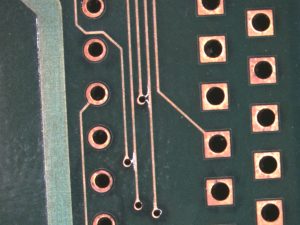
A new Printed Circuit Board (PCB) manufacturer was selected and asked to submit qualification samples of a legacy PCB product. Continuity testing on the as-manufactured raw PCB revealed the presence of open circuits.
The Approach
Coupons were excised from three different PCB and via hole size regions for vertical and horizontal cross-section preparation. Vertical cross-sections were used for via and plated through hole (PTH) plating thickness analysis, inner and outer layer interconnect characterization, laminate characterization, etc. Horizontal sections were used for registration characterization, etc. Careful mechanical sectioning, with close attention to grinding feeds and speeds is the key to good sample preparation. In-process examination using Optical Microscopy (OM) was used to monitor polish quality and location accuracy. Chemical etching was performed to enhance detail in failure areas. Chemical etching can disguise anomalies as well as enhance their appearance, so critical components of etching involve factors such as etchant selection, etching times and application techniques.
The prepared sections were examined by Optical Microscopy (OM), in the as-polished (pre-etch) and after chemical etch (post-etch) states.
The Results
Examination of the vertical cross-sections revealed anomalies (subtle separations) present at the via barrel / inner-layer interconnect interfaces at the electroless copper / inner-layer copper foil interface. The cause was incomplete etch-back/de-smearing procedures after hole drilling. Horizontal cross-section analysis showed that the subtle separations also covered most of the circumference of the vial barrel / inner-layer interconnect interface.