Failure Analysis of a Motorcycle Suspension
Failed metal parts can have catastrophic consequences depending on the application. In a motor vehicle, a failure when the vehicle is traveling at high speeds could be fatal.
Failure Analysis of a Motorcycle Suspension
Summary
Failed metal parts can have catastrophic consequences depending on the application. In a motor vehicle, if the part fails while the vehicle is traveling at high speed, a horrible accident could result. Determining the mechanisms of a failure can help correct the problem or lead to product improvements. This note shows the application of a variety of microscopy techniques to examining and determining the likely cause of a failed motorcycle fork.
Introduction
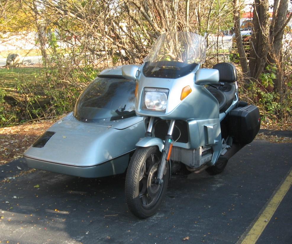
The steering mechanism of a motorcycle uses a triple clamp assembly to hold the telescoping front fork tubes and headset bearings. These assemblies pivot to steer the motorcycle. The lower clamp is larger than the upper clamp and carries much of the mechanical load from the front wheel, brakes and suspension into the bike’s frame.
The lower clamp on this motorcycle had been modified by an after-market company, to change the steering geometry as part of the installation of a sidecar. Installing a modified triple clamp minimizes the cost of adding a sidecar to a motorcycle. This modification is usually done to minimize the effort needed to steer the motorcycle when a sidecar is attached.
For this particular situation, the lower clamp was modified by cutting and welding. After a while the vehicle acquired a persistent pull to the right, and the owner suspected the modified triple clamp as the cause.
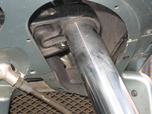
When the assembly was taken apart a crack in the clamp around the modification of the left fork tube was found. The damage was so bad that the fork tubes were out of parallel. The damaged part was replaced and a catastrophic failure was averted. But what went wrong?
Optical Microscopy
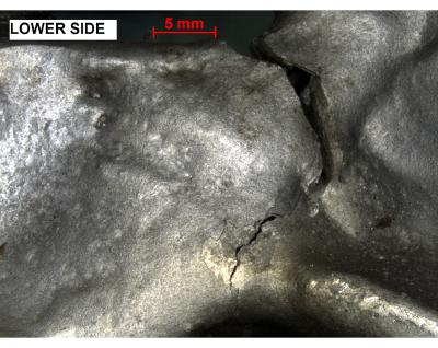
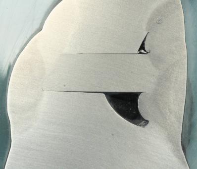
Visualizing the problem is typically a first step, and optical microscopy gave a good view of the extent of the cracking. Surprisingly the cracking was very complex and at least eight surfaces were be observed.
X-Ray Microscopy
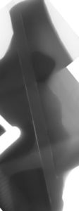
An x-ray microradiograph showed how the modifications to the clamp were made. The radiographs show that a large amount of metal was removed and a new piece of metal placed in the cut to shim the assembly back to the correct width, rather than just saw cut and weld together again.
The shim was anchored to the original equipment manufacturer’s (OEM) portions of the clamp by welding at the exterior surface. This welding did not penetrate anywhere close to the entire thickness of the part. In the radiograph, long narrow gaps (red arrows) can be clearly seen on both sides of the shim.
Metallographic Analysis
In the area where the shim was attached, the fused zones of the welds add up to much less than the original thickness of metal in the clamp, and there is a large void visible in one of the sections.
The micrographs also tell us that three different alloys are now present in the modified area. The original alloy in the clamp is very fine grained, with no apparent flow lines, aligned structures, or solidification structures (A). The shim on the other hand is wrought alloy and is different in morphology from the OEM material (B) and the weld can be seen as (C). The data indicates that they used a copper-containing family of aluminum alloys that can be heat treated to improve their strength. In general, these alloys can also be welded successfully.
SEM-EDS
SEM-EDS provided both very high magnification images of the failure region as well as elemental information. As suspected, the OEM alloy in the lower clamp contains copper, in an amount common to several heat-treatable alloys. The other alloying elements present are also consistent with these materials. These alloys are strong, with mechanical properties approaching those of some grades of soft steel.
The weld filler is an aluminum-silicon alloy. Silicon lowers the melting point of the aluminum, and helps it flow easily, which reduces porosity in welds and castings. These alloys are also strong and stiff, and commonly used in mechanical applications. The weld filler metal solidified in a cavity or void, as shown in the micrograph below.
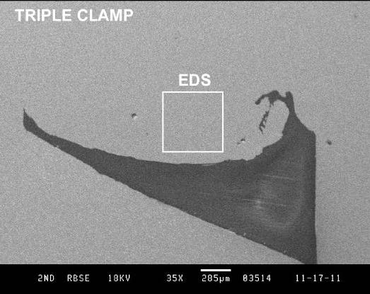
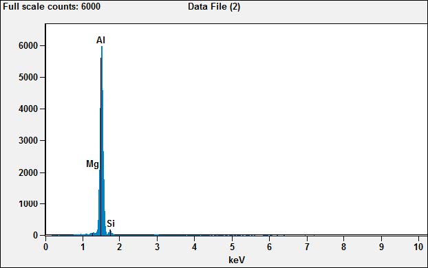
The EDS spectrum, averaged over the area marked in the figure above, showed aluminum, magnesium and silicon.
The shim is an aluminum-magnesium alloy. These alloys are common in wrought form. They are not especially strong or stiff but are valued more for their wide availability in a variety of useful shapes, and their good malleability and ductility. This material mismatch may have contributed to the failure.
More importantly, two areas in the fracture region show tool marks relating to machining the clamp and fitting the shim. A properly executed weld would have obliterated these textures. Finally, the portion of the weld filler that solidified in an open cavity offered no bond to the sides.
In addition to the poor rework of the part there is another more important finding. Large areas of fatigue, in both the OEM metal and in the shim are visible and there is also a small area of overload in weld filler.
Conclusions
The fracture initiated and propagated by fatigue. As the load carrying area became increasingly reduced, the failure continued to propagate by overload through the weld.
Failures that initiate by fatigue indicate a mismatch between the part and the load it must carry.
In this instance, adding the sidecar undoubtedly increased the load, while reduced load-carrying area in the welds, and possibly a poor choice of material in the shim, compromised the ability of the part to carry that increased load.